USBPD-Stack
Cross-platform distribution of the NXP USB Power Delivery stack for the PTN5110.
Code on GitHub ↗USBPD-Stack is an open-source distribution of the NXP MCUXpresso USB Power Delivery stack (derived from MCUXpresso middleware 25.06.00): it keeps the proven PTN5110 TCPC driver and adds a modern build system, a portable HAL layer and multi-platform ports. The ST-LINE value-add is portability: the same PD policy engine runs on ESP32-S3, STM32 and Arduino by swapping only the adapters. This page summarises the repository README, usage guide and wiki; the authoritative reference remains GitHub.
Origin and value-add
The PD core (policy engine and PTN5110 driver) comes from the NXP MCUXpresso USB PD stack — code already proven in compliance. ST-LINE does not rewrite the protocol: it repackages it into a clean structure, with a sharp separation between inherited NXP code (third_party/nxp_pd/) and its own additions.
The original contribution is the portability layer: header-only HAL adapters for GPIO, I²C and OS primitives, scheduling ports per platform, a PlatformIO-ready layout and compile-time target selection. Dual-licensed: BSD-3-Clause for the NXP sources, MIT for the ST-LINE parts.
What it does
USB Power Delivery 2.0 / 3.0 policy engine with PTN5110 Type-C Port Controller support. It handles Source, Sink and DRP roles, capability discovery, PDO/RDO contract negotiation and power transitions.
Optional features enabled by configuration: DisplayPort alt mode, PD 3.0 Programmable Power Supply (PPS) and Fast Role Swap (opt-in).
USB Power Delivery concepts in brief
USB Power Delivery (PD) is the protocol that lets two devices over Type-C negotiate voltage and current well beyond the 5 V / 3 A of the classic USB bus — up to 240 W with the Extended Power Range. A handful of terms recur throughout the documentation:
- Source / Sink — who supplies and who draws power. A DRP (Dual-Role Power) can do both and swap roles at runtime.
- PDO / RDO — the Source advertises its capabilities as a list of Power Data Objects (e.g. “5 V 3 A”, “9 V 3 A”, “20 V 5 A”); the Sink picks one and answers with a Request Data Object that fixes the power contract.
- TCPC — Type-C Port Controller, the chip (here the PTN5110) that implements the PD PHY and the cable’s physical interface; the software policy engine, running on the MCU, decides roles, capabilities and transitions by talking to the TCPC over I²C per the TCPCI interface.
- PPS — PD 3.0 Programmable Power Supply: voltage adjustable in fine steps (20 mV) for direct battery charging.
The USBPD-Stack policy engine is exactly the state machine that orchestrates this dialogue; the PTN5110 driver is the bridge to the silicon.
Supported targets
ESP32-S3 (ESP-IDF) — FreeRTOS + HAL, Stable: 1 kHz tick via a shared FreeRTOS software timer.
STM32 F3/F4/H7 — FreeRTOS + Cube HAL, Stable: EXTI-based ALERT handling, configurable I²C timeout.
Arduino (AVR/ESP/NXP) — cooperative loop, Beta: uses TwoWire for I²C; PD_PortArduino_TaskTick() must be called from the main loop.
Exactly one PD_CONFIG_TARGET_* macro is selected before compiling; each platform has its own pd_phy_<platform>_config_t structure describing the required MCU resources.
Architecture
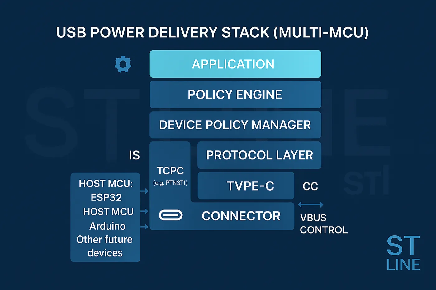
include/ — core public headers (policy engine, configs, types). src/ — core C sources: Policy Engine (usb_pd_policy.c, the PD state machine), Device Policy Manager (usb_pd_interface.c, creates PD instances and dispatches events), protocol timers (usb_pd_timer.c) and alt mode.
third_party/nxp_pd/ — PTN5110 driver and inherited NXP code (TCPC register access, ALERT interrupts, bus recovery). support/ — HAL abstraction (GPIO, I²C, OS primitives) and its per-platform implementations. port/ — scheduler glue that periodically invokes PD_TimerIsrFunction.
Porting the stack to a new MCU essentially means implementing only the support/ layer (plus the scheduling port): the core and the PTN5110 driver remain unchanged.
Configuration
All options live in include/usb_pd_config.h. Beyond target selection (PD_CONFIG_TARGET_ESP32S3 / _STM32 / _ARDUINO; defaults to ESP32-S3 if none is set) the main flags are: PD_CONFIG_MAX_PORT (simultaneous PD ports), PD_CONFIG_ALT_MODE_SUPPORT / _DP_SUPPORT (DisplayPort alt mode), PD_CONFIG_PD3_PPS_ENABLE (PPS), PD_CONFIG_SOURCE_ROLE_ENABLE / _SINK_ROLE_ENABLE (restrict advertised roles), PD_CONFIG_PD3_FAST_ROLE_SWAP_ENABLE.
Macros are set from the build system (build_flags in PlatformIO, add_compile_definitions in CMake). Include paths to add: include/, port/include, support/include, third_party/nxp_pd/include; sources to compile: src/, port/src, support/src, third_party/nxp_pd/src.
Integration
Prerequisites: a PTN5110 connected over I²C with the ALERT pin on an edge-interrupt-capable GPIO, correct SDA/SCL pull-ups and a C toolchain for the target (ESP-IDF, STM32Cube, Arduino, PlatformIO).
Typical flow: (1) describe the hardware in pd_phy_<platform>_config_t (SDA/SCL GPIOs and priorities for ESP32-S3; I2C_HandleTypeDef*, ALERT pin and IRQ for STM32; TwoWire* and pull-ups for Arduino); (2) fill pd_instance_config_t with roles and PDO tables and phyType = kPD_PhyPTN5110; (3) implement the pd_stack_callback_t and pd_power_handle_callback_t callbacks; (4) call PD_InstanceInit; (5) run PD_InstanceTask in a FreeRTOS task or the Arduino loop, keeping the shared 1 ms tick active.
Why the tick is 1 ms, and not 10
The shared 1 ms tick is not a convenient convention: it is the number that falls out of requiring the protocol timers to land inside their windows. PD does not define point deadlines but intervals — the tightest is tSenderResponse, between 24 and 30 ms: answering before 24 ms or after 30 ms violates the protocol equally.
The usable window is therefore 6 ms wide, and a tick of period T introduces up to T of quantization error on the deadline, because the state machine can only notice elapsed time at the next tick:
| Tick period | Worst-case error | % of the window | Ticks in the window | Verdict |
|---|---|---|---|---|
| 0,5 ms | 0,5 ms | 8,3 % | 12 | usable |
| 1 ms | 1 ms | 16,7 % | 6 | usable |
| 2 ms | 2 ms | 33,3 % | 3 | usable |
| 5 ms | 5 ms | 83,3 % | 1 | marginal |
| 10 ms | 10 ms | 166,7 % | 0 | out of spec |
| 20 ms | 20 ms | 333,3 % | 0 | out of spec |
At 1 ms the uncertainty is 17 % of the window and six ticks fit inside it: there is margin for both the quantization error and the I²C response latency towards the TCPC. At 5 ms quantization alone eats 83 % of the window and nothing is left for the rest. At 10 ms the window is blown by the tick alone: this is not marginal performance, the deadline can be missed.
It is also why the tick must be shared and not duplicated: two independent software timers driving the same stack add up their quantization errors, and on a 6 ms window the sum shows. On FreeRTOS platforms it is also worth checking that configTICK_RATE_HZ is at least 1000, because a slower system tick is a floor under any software timer built on top of it.
What a new port actually takes
“You only implement the support/ layer” is true but does not say how much work that is. Concretely the layer must provide four things, and these are what decide whether a platform is suitable:
What the support/ layer must provide |
Why the stack needs it |
|---|---|
| I²C: blocking 8-bit register read and write, with timeout | it is the only channel to the TCPC: every state-machine transition becomes a register access |
| GPIO: one input with falling-edge interrupt (ALERT) | the TCPC cannot be polled without losing events: it signals and must be serviced |
A 1 ms periodic tick calling PD_TimerIsrFunction |
it is the time base of every protocol timer — see the arithmetic above |
| OS primitives: a task or a loop, and mutual exclusion on the I²C | the bus is shared with the rest of the application; the ALERT ISR and the task must not access it together |
An MCU’s eligibility therefore comes down to two questions: does it have a GPIO with edge-triggered interrupt (not just level) and can it guarantee a 1 ms tick? If yes, the port is mechanical. If the answer to the second is no — typical of heavily loaded cooperative loops — the problem is not solved in the support/ layer: it is solved by lightening the loop, and that is why the Arduino target is declared Beta and not Stable.
The CC resistors: why they never appear in software
A question that recurs during integration: where do you set the 3 A to advertise? The answer is that you do not set it in the stack’s software. Before PD comes into play, Type-C declares its intentions with resistors on the CC lines, and the one reading them is the TCPC:
| Resistor | Value | Who fits it | What it declares |
|---|---|---|---|
| Rp | 56 kΩ | Source | default USB only (500/900 mA) |
| Rp | 22 kΩ | Source | 1,5 A a 5 V |
| Rp | 10 kΩ | Source | 3 A a 5 V |
| Rd | 5,1 kΩ | Sink | “I am a sink” |
| Ra | ≈ 1 kΩ | active cable | “I am a cable, not a device” |
This level — called Type-C, not Power Delivery — works with no PD at all: it is why a Type-C charger with no PD delivers 3 A to a phone without exchanging a single message. PD comes in above it, to go beyond 5 V. In the PTN5110 the Rp and Rd are internal and switched by register, so the stack governs them indirectly through the role it declares: there is nothing to fit on the PCB beyond the Rd if the device is a sink-only design without a TCPC.
Diagnostics and platform notes
Diagnostics: enable the debug macros in usb_pd_config.h to trace the message exchange; PD_Control(..., PD_CONTROL_GET_PD_STATE, ...) returns the current state-machine node; the PTN5110 driver exposes helpers to read fault status and regulate VBUS.
ESP32-S3: the adapter installs a 1 ms timer and uses the i2c_instance I²C driver instance from pd_phy_esp32s3_config_t; PD_InstanceTask runs in a dedicated task and the timer callback is registered as soon as an instance exists.
STM32 (F3/F4/H7): requires Cube HAL handles and FreeRTOS; supply the HAL I²C pointer, ALERT GPIO info and IRQ priorities in pd_phy_stm32_config_t, and the adapter handles EXTI dispatch via PD_PortStm32_DispatchExti. Arduino: cooperative design, call PD_PortArduino_TaskTick() and PD_InstanceTask() inside loop(), I²C over TwoWire.
Compliance, status and roadmap
docs/library_usage.md holds the step-by-step integration guide; docs/compliance_test_report/ collects Ellisys captures from the original NXP stack. Initial release 0.1.0 (2025-11-06); development on the develop branch.
Stated roadmap: a FUSB302B TCPC port layer with ALERT-handling helpers, refreshed Ellisys compliance reports on the new platforms and ready-to-build example projects for each target. References: PTN5110 product page (NXP) and the USB Type-C Port Controller Interface Specification (UM11056).
A similar project?
Acoustics, embedded, calculation tools: if you have a related use case, let’s talk.